

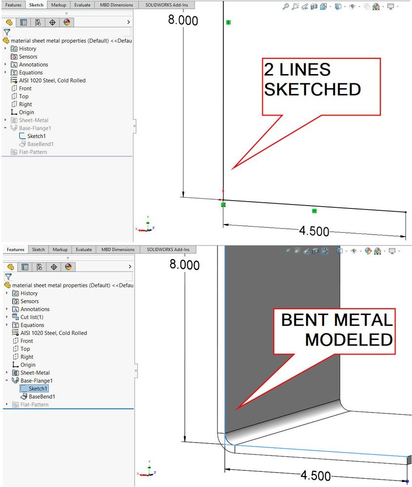

FIGURE 1. CAD makes it straightforward to mannequin sheet steel. Only a easy 2D line sketch (higher display shot) can management radii and thickness that may precisely unfold (decrease display shot). Some requirements could apply.
Editor’s Notice: Recordsdata related to this column, one in all which is a pattern half that makes use of a gauge desk that was as soon as used for sheet steel manufacturing, will be downloaded right here.
The incorporation of sheet steel in a product presents quite a few design-for-manufacturing alternatives. These in flatwork trades learn about requirements—for gauges of thickness, tempers of alloys, greatest practices in radii, tooling entry, springback, stress reduction, and extra.
Since its inception, mainstream 3D CAD has supplied handy modeling with glad compliance to requirements. These within the CAD commerce know that simply a few sketched traces can create a visually correct 3D mannequin that predicts the truth of air bending fairly properly. Determine 1 reveals an instance of modeling an L bracket with two sketched traces.
As a aspect observe, full-blown CAM will be built-in into the 3D CAD design seat. Right here we exclude the CAM options and instruments. With the ability to produce a flat structure with a design software helps keep away from false begins and is usually adequate for fabrication of a one-off prototype.
Determine 1 reveals a 2D sketch (higher display shot) that’s used to create a 3D mannequin (decrease display shot). From a easy line sketch, the software program takes care of modeling the bend radius, the uniform thickness, the impartial bend line, the route of thickness, and the bend size (Z route).
The place applicable, all modeling controls are primarily based on consumer choice from requirements offered by varied dropdowns, radio buttons, and information entry fields.
The Predictable Strategy of Bending
Earlier than exploring a brand new CAD software/trick, let’s dive into what’s previous information to those that understand it and maybe helpful perception for individuals who simply inherited a Pexto: Bending sheet steel, whether or not in a leaf brake, folder, or a press brake, is a predictable course of.
The impartial bend line is imaginary. It doesn’t change in size because the sheet steel is bent. As a share of thickness, the k-factor locates the place the impartial line is, which in flip predicts the size in flat structure.
Determine 2 illustrates air bending of a sheet steel half, with a stationary backside V die offering three traces of contact and an higher punch offering one line of contact.
These three traces of contact are all that may ever be touching throughout the bending cycle.

FIGURE 2. A stationary V die supplies three-point contact with the workpiece. The tip of the higher software presses the workpiece into place within the valley, by no means totally coining it.
The workpiece have to be positioned to find the wanted bend. If a backstop isn’t obtainable on the machine, visible aiming is a routine resolution.
The flat structure will be utilized to scribe traces the place the bending punch tip will make contact within the heart of the bend. Aiming marks for the bending course of can embody a laser-scribed bend line or maybe carved notches within the edges. Nonetheless, notching little bend targets will be tedious. (That will be foreshadowing.)
Returning to Determine 2, because the punch strikes downward, the punch tip presses the sheet steel into the valley of the decrease die. Within the air bending course of, the sheet steel isn’t coined towards the V die; it’s merely overpressed into the specified angle and allowed to spring again into perfection.
You earn the Lengthy-Time period Reader Benefit Badge when you seen that Determine 2 is a repeat from the July 2017 episode of this column.
A Good Okay-Issue Improves the Purpose
The quantity of coining and the dimensional options of the tooling introduce variables in the best way the sheet steel responds to being pushed past its yield level.
These tooling variations have predictable outcomes on the stretch of the steel, represented as a k-factor in CAD. For a given setup of tooling in a press brake and for a given gauge and alloy of sheet steel, a really correct prediction of the flat structure is straightforward. The default k-factor (0.50) is often shut. It would matter so much if there are a number of bends within the design.
Fabricating retailers usually publish their gauge tables (or different strategies of calculation) to indicate k-factors that work with varied tooling and gauge alternatives.
A CAD Trick for Bend Notches
Determine 3 presents an answer to the tedium of including bend notches. Utilizing a CAD software circa 2024, I imagine, choose Insert>Sheet Metallic>Bend Notch, ensuring the flat sample is unsupressed. The ensuing aiming notches solely exist within the flat structure for export, so if you wish to see what the bent bend notches would possibly appear to be, merely export and import the flat, convert it to sheet steel, and add a sketched bend.
To resolve the foreshadowing, bend notches are now not tedious little Lower-Extrudes. The k-factor is the important thing to success with aiming the bend notches for aiming, because it had been.
Match the k-factor to the tooling and materials and pleasure shall be at hand. The default k-factor of 0.50 locates the impartial line 50% of the best way into the fabric. It’s extra more likely to be between 0.36 and 0.44, however that’s fairly shut. For optimum outcomes, contact your native press brake operator.

FIGURE 3. Bend notches will be inserted right into a flat sample. There are settings for controlling the dimensions and form of the bend notch. The notches shall be exported within the 2D flat sample however shall be suppressed within the fashioned 3D mannequin.


