
Mainstream 3D CAD is nice for sheet steel initiatives. It’s a software with which to make well-behaved sheet steel fashions which might be each visually and mechanically correct—helpful for producing flat patterns and different predictions of the sheet steel altering form beneath the affect of tooling. Relating to predicting the habits of a sheet materials like leather-based beneath the affect of stitching, 3D CAD stays an ideal planning useful resource.
Determine 1A is taken (with out permission) from packaging for a product supplied by Tandy Leather-based. The dopp equipment is a troublesome leather-based field to stuff in a suitcase when touring. I’ve made a number of as items, and so they’re at all times well-received. Tandy’s equipment is totally prepared for meeting. Having the piece components punched and cut-to-size is what makes the equipment so user-friendly.
CAD got here into play after I was making a stiffer-walled variation of Tandy’s design. Determine 1B reveals a number of the modifications in what we’ll name the FMA Field. It has related flop-over lid however replaces the tie strap within the unique design with a latch. The latch works greatest with stiff partitions, thus the necessity for stiffening panels lined with an internal field liner.
Plan in 3D for the 2D
Seen in 3D, the mannequin resembles the completed merchandise. To generate flat patterns in 2D, a CAD trick is used to flatten the “unattainable” sheet steel corners. However earlier than being tough, there’s extra about objectives for the 3D mannequin.
As with Tandy’s design, a pair of finish caps are sewn into place to kind the oblong field. The floppy flaps on the top panels assist retain no matter contents is likely to be within the field when the lid is latched.
A hemmed edge in the principle body provides stiffness to the field’s opening. One nook of a tab of the top panel can be trapped inside that hemmed edge. A spacer (not proven) inside many of the size of the hem retains it open and provides stiffness.
Store Tooling as a Design Constraint
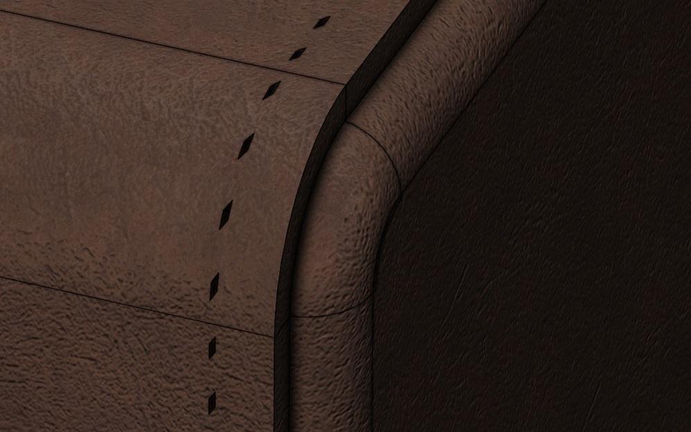
An necessary design constraint within the FMA Field is its sewn seam. Determine 1C is a closeup of one of many corners prepared for stitching. The sewn overlap of finish panel with principal body controls the field’s completed dimension.
The guide stitching method used on this challenge is saddle stitching requiring prepunched holes. For punching by hammer blow, forked tooling is out there to make as much as six holes per stroke on 5-mm spacing.
The 5-mm PERF PATH in Determine 2A is a consequence of the 5-mm tooling fork. The punch software works nice when the principle body is flat. A two-pronged fork works when going across the corners. The tip panels can be punched to match this perforation path.

FIGURE 1A. The industrial design from Tandy Leather-based’s dopp equipment is the inspiration for a CAD challenge.
A CAD tip concerning linear patterns is proven in Determine 2B. The linear sample of sew holes has situations skipped the place the hem is shaped.
The flat sample for the principle body exhibits the placement of the stiffening panels. This was achieved by creating blind (0.004 in. deep on this instance) Reduce-Extrudes in the principle body so their profiles present up within the flat sample.
The flat sample for the top panel is proven in Determine 2C. As with the principle body, it will likely be printed one-to-one after which used to switch to the leather-based workpiece.
When the bends in the principle body are shaped, the within interval between punched holes will shrink across the bends. Wanting again at Determine 1C, the holes going across the corners on the top panel can be lower than 5 mm when shaped and better than 5 mm when the top panel is within the flattened situation.
Odd Sheet Steel with Suppression Points
The tip panels have been modeled as typical sheet steel with open corners. Within the shaped configuration (named the acquainted Default on this instance), a sweep was modeled and mirrored to fill within the open corners and provides the phantasm of a cup-formed nook. The sweeps have been helpful for modeling the perforation sample to align with the principle body. The sweeps and the perf holes are suppressed within the flat sample configuration (named DefaultSM-FLAT-PATTERN, on this instance).
When the DefaultSM-FLAT-PATTERN configuration is lively, a Base-Extrude and a Reduce-Extrude (for the sew holes) are unsuppressed to fill within the open corners and to finish the sew path within the flat situation.
Some effort was made with the sources of 3D CAD to regulate the dimensions, the bend radii, and the seam overlap to get the punched sew holes in each corners of the top panels to be symmetrical and similar. This was a course of that required a number of iterations.
One of the best success in iteration was had by forcing the principle body’s perforation sample to go across the corners properly in each shaped and flat situation. Then the top panel’s sample was constrained to the principle body’s gap location.
The 3D mannequin makes it sensible to look at the advance and retreat of the linear sample as the principle body’s dimension is edited. Beginning with the entrance flap, regulate the bend radius for the flap to reach with the sample advancing across the nook and throughout the highest properly. Then repeat for the highest rear bend, and so forth throughout the sewn path.
Success from Planning
Determine 3 compares prediction to actuality. The finished field contains a carved trough to maintain the thread beneath floor that the CAD plan lacked. It additionally has a latch that wasn’t modeled. Aside from that, the resemblance is robust with this one.

FIGURE 1B. The FMA model of the field has a latch (not specified) as a substitute of a strap for closure. The partitions are stiffened with skinny cardboard panels which might be glued in a sandwich between the outer leather-based and the internal liner (deer pores and skin on this challenge). We additionally stretched the width a bit to work to accommodate a roll of 8-1/2-in.-wide paper.
By way of precision, it’s inside ¼ in. within the unconstrained situation. It may be stretched or shoved into higher than 1/16-in. tolerance, however the radii within the leather-based chill out as quickly as you let go.
For the artful, this challenge used a Okay-factor of 0.5 for 0.090-in. materials. The sandwich of internal liner and outer leather-based turned out to vary between 0.070 and 0.1 in. From entrance flap to rear wall is 3-3/4 in.—the objective was 4 in. Vertically, the expected 4-3/16 in. arrived at 4-1/8 in. The general width was purported to be 8-13/16 in. and completed at 8-3/4 in., and the underside nook radii have been near predicted at ½ in.
The primary advantages of expending the trouble in 3D CAD have been within the punching plan for the stitching within the corners and in getting the stiffening panels positioned appropriately. The end result was nearly as straightforward as Tandy’s to assemble.
Within the subsequent episode, we’ll contemplate using a Swept-Flange to mannequin the “unattainable” corners as a substitute of the configuration/suppression trick proven right here.


